高速道路の技術開発
- コーポレートトップ
- 事業案内
- 技術・環境・海外事業
- 高速道路の技術開発
安全・安心な高速道路を提供するための技術を開発しています
維持管理業務プロセスの変革

点検から補修までの一連の業務プロセスにおいて、SMH※開発技術を活用し、生産性を倍増するとともに、意思決定プロセスを標準化することで業務の品質向上を目指す
-
SMH(スマートメンテナンスハイウェイ)
・・・・
高速道路の長期的な「安全・安心」の確保のために、ICTやロボティクスなど最新技術を活用し、高速道路のアセットマネジメントにおける生産性を飛躍的に向上するためのプロジェクト
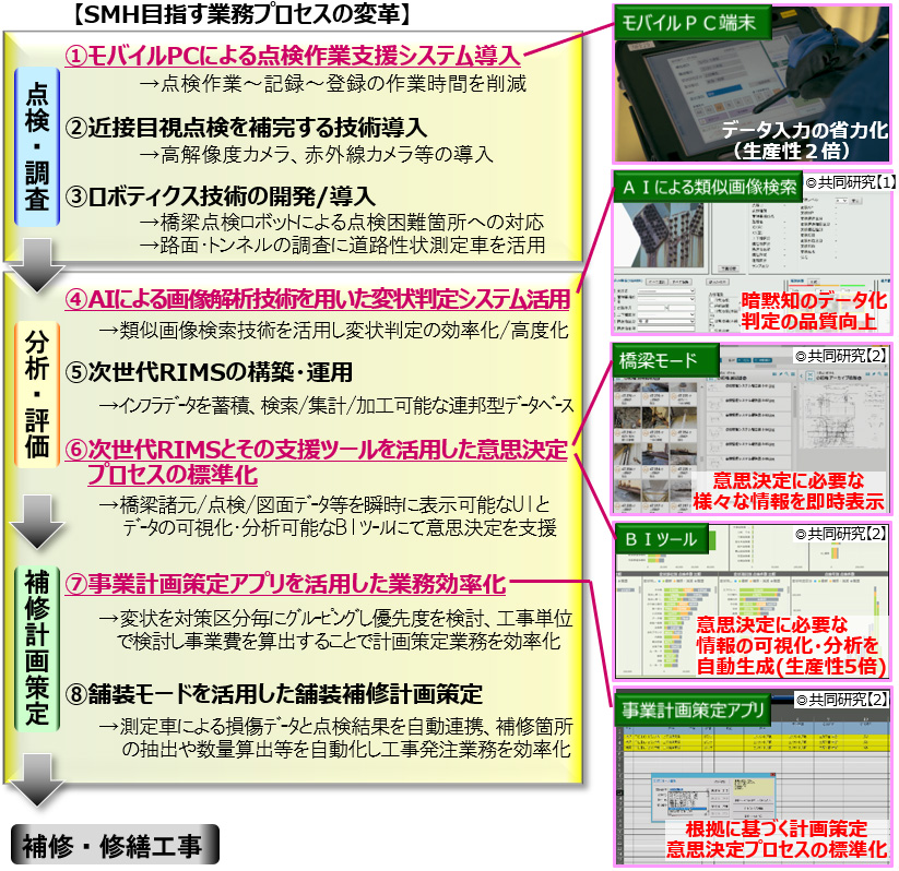
◎共同研究【1】:北海道大学大学院情報科学研究院 メディアダイナミクス研究室と共同研究にて開発中
◎共同研究【2】:東京大学大学院情報学環外部と共同研究にて開発中
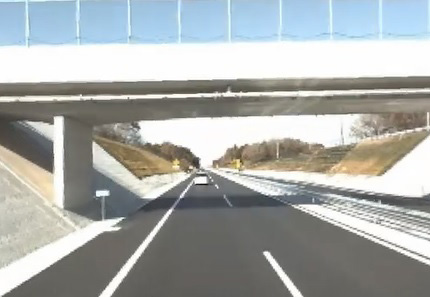
全周囲道路映像の維持管理業務基盤としての活用
◎共同研究【3】
現地状況(本線/側道/高架下等)を瞬時に把握することができ、映像内の距離計測が可能。
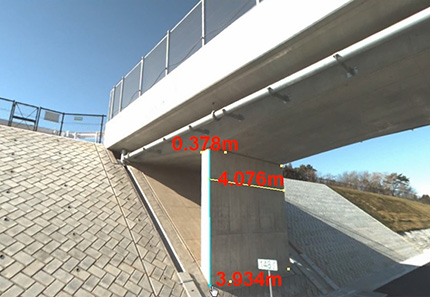
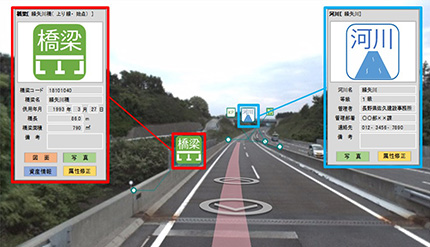
◎共同研究【3】:株式会社トリオンと共同研究にて開発中
MR※(複合現実)技術を活用した技術者育成ツール
◎PRETES-e
※MR(Mixed Reality:複合現実)・・・・実空間と仮想空間を融合させる技術
MR技術にて橋梁の内部構造を可視化することによって、設計・施工上の特徴、代表的な変状と劣化メカニズム等について教育ができ、より理解度が高く効果的な研修が可能
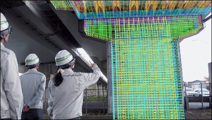
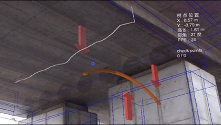
◎PRETES-e:株式会社ネクスコエンジニアリング北海道にて開発中
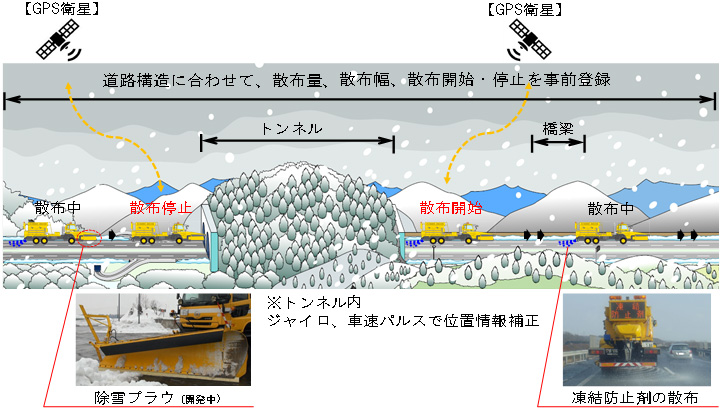
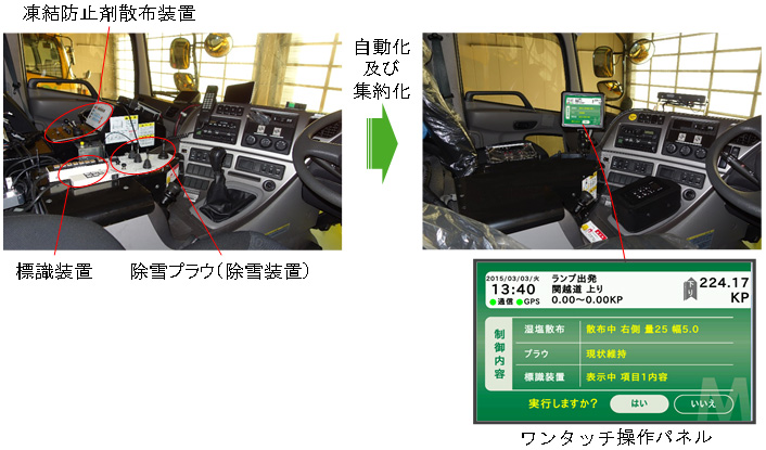
位置情報を活用した凍結防止剤の散布作業自動化
本システムは、GPSの位置情報と凍結防止剤の散布装置を連動させ、散布を自動制御する装置です。システムには、トンネルや橋梁など道路構造に合わせた凍結防止剤の「散布量」、「散布幅」、「散布開始・停止」の作業内容が予め登録されており、オペレーターは作業開始前に実際に走行する「作業区間」をセットするだけで、適確に凍結防止剤の散布作業を行うことができます。
また、手動で操作する場合でも、運転席に設置している複数の操作装置を一つの画面に集約しワンタッチ操作が可能となりました。
添付資料
位置情報を活用した凍結防止剤の散布作業自動化(平成30年11月1日 定例記者会見資料)【PDF:428KB】
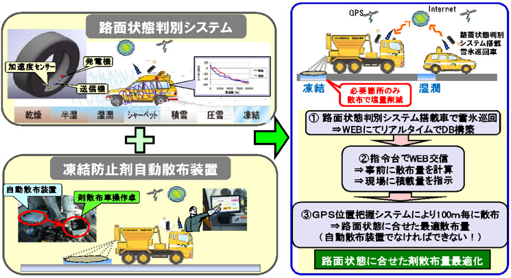
凍結防止剤自動システム(ISCOS)の導入
ISCOSは、CAIS®から得られた路面判別データを基に凍結防止剤の最適な散布量を把握し、凍結防止剤自動散布装置により散布区間・散布量を自動制御することで路面状況に応じた自動散布を実現した、世界初の技術です。
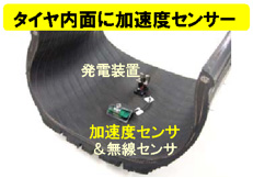
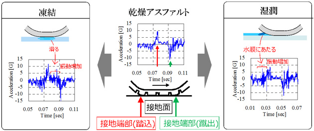
【CAIS®の概要】
タイヤ内部の加速度センサから得られる路面状況に応じた特徴的な振動波形をもとに、凍結・湿潤などの路面判別を行う
- ISCOS(Intelligent Salting Control Optimization System):(株)ネクスコ・エンジニアリング北海道 &(株)ブリジストン特許技術
- CAIS(Contact Area Information Sensing):(株)ブリジストン特許技術
【ISCOSの概要】
CAIS®の路面判別結果は、リアルタイムにインターネット経由でWEBサーバに送信され、データベースが構築されます。そのデータを基にWEBアクセスすることで、100mごとの路面状態に合わせた最適散布量を計算可能です。自動散布装置を搭載した凍結防止剤散布車は、自動でWEBアクセスし路面データをダウンロードします。凍結防止剤散布車は走行するだけで自動的に散布作業を実施するものです。
添付資料
凍結防止剤自動システム(ISCOS)の導入について(平成28年10月26日 定例記者会見資料)【PDF:420KB】
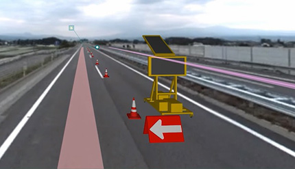
Road Zipper®Systemの導入・活用
NEXCO東日本グループでは、
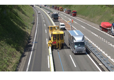
- 工事規制等において通行車線と作業エリアをコンクリート防護柵にて完全に分離することによる「安全性の向上」
- 車線規制の切替え等、規制を迅速に実施することによる工事全体の「作業効率性の向上」
- お客さまのご利用の多い時間帯に合わせた工事規制範囲・通行車線数の変更による「工事規制渋滞の抑制」
を目的に、Road Zipper®Systemを導入・活用しております。
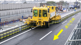
Road Zipper®System (ロードジッパ-システム)の概要
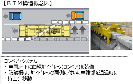
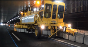
Road Zipper®Systemは、コンクリート防護柵 (Concrete Reactive Tension System)の設置位置を専用の防護柵切替車両 (Barrier Transfer Machine、以下「BTM」という)により移動させることができるシステムです。
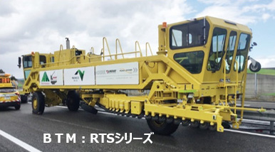
《BTM》※RTSシリーズ(左記写真)諸元
- 重量:空車時約22t、輸送時19t (コンベア部取外し)
- 走行速度:作業時 5~15km/h、回送時 20~30km/h
- 防護柵の移動幅:3~5.5m/回

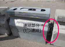
重量:約680kg/個、延長:1000mm
高さ:810mm、幅460mm
重量:約306kg/個、延長:1000mm
伸縮可能な鋼製エクステンを一定間隔に配置
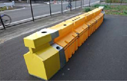
開口部(端部)に衝突緩衝用として設置
規制速度(衝突速度)に合わせて数量を変更
Road Zipper®System (ロードジッパーシステム) の導入
Road Zipper®Systemは、米国(アメリカ)のLindsay Transportation Sales & Service LLC(以下「LINDSAY社」という)が開発・製造・販売しており、現在、日本では(株)ネクスコ東日本イノベーション&コミュニケーションズ(NI&C)が国内での販売・リース等を行っています。
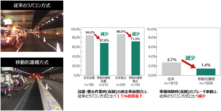
なお、Road Zipper®Systemの日本導入にあたっては、ネクスコ東日本において、本システムの車両への影響等の確認検証を行っており、従来のラバコンによる規制方法と比較して有用性を確認しております。
Road Zipper®System (ロードジッパーシステム) の活用
| 路線・区間 | 工事内容 | 概要 |
|---|---|---|
| 常磐自動車道 柏IC~流山IC | はく落対策工事 | はく落対策工事の工事車線規制において、ロードジッパーシステムの作業性確認や交通影響を把握する実証実験として、国内で初めて導入。 |
| 東京外環自動車道 大泉JCT~和光IC | ベルトコンベア設置工事 | 本線トンネル工事から発生する掘削土を運搬する工事設備として、既存区間にコンベアを設置する工事の本線規制に活用。 |
| 関越自動車道 渋川伊香保IC~前橋IC | 付加車線設置工事 | 前橋IC(上り線)出口の減速車線の延伸(付加車線設置)工事において、お客さまのご利用の時間帯に合せた工事規制に活用。 |
| 道央自動車道 北広島IC~恵庭IC | 床板取替工事 | 北広島IC~恵庭IC間の島松川橋における老朽化した鉄筋コンクリート床板の取替え工事の際、お客さまのご利用時間帯に応じて車線数を変更する対面通行規制に活用。 |
| 北陸自動車道 中之島見附IC~長岡JCT | 床板取替工事 | 中之島見附IC~長岡JCT間の高瀬橋(上り線)において、新潟県で初めてとなる大規模な橋梁のリニューアル工事(床版取替工事)の車線規制に活用。 |
はく落対策工事規制状況
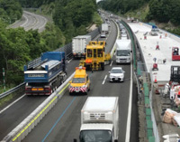
床版取替工事 車線数変更規制状況
床版取替工事規制状況 (施工ヤード拡張)

PDFファイルをご覧いただくには、AdobeSystems社のプラグインソフト「Acrobat Reader(日本語版)」が必要です。お持ちでない方は、こちらからダウンロード(無料)してご利用ください。